2.4. Setting Up and Connecting the Cluster Hardware
After installing Red Hat Enterprise Linux, set up the cluster hardware components and verify the installation to ensure that the members recognize all the connected devices. Note that the exact steps for setting up the hardware depend on the type of configuration. Refer to Section 2.1 Choosing a Hardware Configuration for more information about cluster configurations.
To set up the cluster hardware, follow these steps:
Shut down the members and disconnect them from their power source.
Set up the bonded Ethernet channels, if applicable. Refer to Section 2.4.1 Configuring Ethernet Channel Bonding for more information.
When using power switches, set up the switches and connect each member to a power switch. Refer to Section 2.4.2 Configuring Power Switches for more information.
In addition, it is recommended to connect each power switch (or each member's power cord if not using power switches) to a different UPS system. Refer to Section 2.4.3 Configuring UPS Systems for information about using optional UPS systems.
Set up the shared disk storage according to the vendor instructions and connect the members to the external storage enclosure. Refer to Section 2.4.4 Configuring Shared Disk Storage for more information about performing this task.
In addition, it is recommended to connect the storage enclosure to redundant UPS systems. Refer to Section 2.4.3 Configuring UPS Systems for more information about using optional UPS systems.
Turn on power to the hardware, and boot each cluster member. During the boot-up process, enter the BIOS utility to modify the member setup, as follows:
Ensure that the SCSI identification number used by the HBA is unique for the SCSI bus it is attached to. Refer to Section D.5 SCSI Identification Numbers for more information about performing this task.
Enable or disable the onboard termination for each host bus adapter, as required by the storage configuration. Refer to Section 2.4.4 Configuring Shared Disk Storage and Section D.3 SCSI Bus Termination for more information about performing this task.
Enable the member to automatically boot when it is powered on.
Exit from the BIOS utility, and continue to boot each member. Examine the startup messages to verify that the Red Hat Enterprise Linux kernel has been configured and can recognize the full set of shared disks. Use the dmesg command to display console startup messages. Refer to Section 2.3.3 Displaying Console Startup Messages for more information about using the dmesg command.
Verify that the members can communicate over each point-to-point Ethernet connection by using the ping command to send packets over each network interface.
Set up the shared cluster partitions on the shared disk storage. Refer to Section 2.4.4.3 Configuring Shared Cluster Partitions for more information about performing this task.
2.4.1. Configuring Ethernet Channel Bonding
Ethernet channel bonding in a no-single-point-of-failure cluster system allows for a fault tolerant network connection by combining two Ethernet devices into one virtual device. The resulting channel bonded interface ensures that in the event that one Ethernet device fails, the other device will become active. This type of channel bonding, called an active-backup policy allows connection of both bonded devices to one switch or can allow each Ethernet device to be connected to separate hubs or switches, which eliminates the single point of failure in the network hub/switch.
Channel bonding requires each cluster member to have two Ethernet devices installed. When it is loaded, the bonding module uses the MAC address of the first enslaved network device and assigns that MAC address to the other network device if the first device fails link detection.
To configure two network devices for channel bonding, perform the following:
Create a bonding devices in /etc/modules.conf. For example:
alias bond0 bonding
options bonding miimon=100 mode=1
This loads the bonding device with the bond0 interface name, as well as passes options to the bonding driver to configure it as an active-backup master device for the enslaved network interfaces.
Edit the /etc/sysconfig/network-scripts/ifcfg-ethX configuration file for both eth0 and eth1 so that the files show identical contents. For example:
DEVICE=ethX
USERCTL=no
ONBOOT=yes
MASTER=bond0
SLAVE=yes
BOOTPROTO=none
This will enslave ethX (replace X with the assigned number of the Ethernet devices) to the bond0 master device.
Create a network script for the bonding device (for example, /etc/sysconfig/network-scripts/ifcfg-bond0), which would appear like the following example:
DEVICE=bond0
USERCTL=no
ONBOOT=yes
BROADCAST=192.168.1.255
NETWORK=192.168.1.0
NETMASK=255.255.255.0
GATEWAY=192.168.1.1
IPADDR=192.168.1.10
Reboot the system for the changes to take effect. Alternatively, manually load the bonding device and restart the network. For example:
/sbin/insmod /lib/modules/`uname -r`/kernel/drivers/net/bonding/bonding.o \
	      miimon=100 mode=1
/sbin/service network restart
For more information about channel bonding, refer to the high-availability section of the Linux Ethernet Bonding Driver Mini-Howto, available in:
/usr/src/linux-2.4/Documentation/networking/bonding.txt |
 | Note |
|---|---|
You must have the kernel-source package installed in order to view the Linux Ethernet Bonding Driver Mini-Howto. |
2.4.2. Configuring Power Switches
Power switches enable a member to power-cycle another member before restarting its services as part of the failover process. The ability to remotely disable a member ensures data integrity is maintained under any failure condition. It is recommended that production environments use power switches or watchdog timers in the cluster configuration. Only development (test) environments should use a configuration without power switches. Refer to Section 2.1.3 Choosing the Type of Power Controller for a description of the various types of power switches. Note that within this section, the general term "power switch" also includes watchdog timers.
In a cluster configuration that uses physical power switches, each member's power cable is connected to a power switch through either a serial or network connection (depending on switch type). When failover occurs, a member can use this connection to power-cycle another member before restarting its services.
Power switches protect against data corruption if an unresponsive (or hanging) member becomes responsive after its services have failed over, and issues I/O to a disk that is also receiving I/O from another member. In addition, if a quorum daemon fails on a member, the member is no longer able to monitor the shared cluster partitions. If power switches or watchdog timers are not used in the cluster, then this error condition may result in services being run on more than one member, which can cause data corruption and possibly system crashes.
It is strongly recommended to use power switches in a cluster. However, administrators who are aware of the risks may choose to set up a cluster without power switches.
A member may hang for a few seconds if it is swapping or has a high system workload. For this reason, adequate time is allowed prior to concluding another member has failed (typically 15 seconds).
If a member determines that a hung member is down, and power switches are used in the cluster, that member power-cycles the hung member before restarting its services. Clusters configured to use watchdog timers self-reboot under most system hangs. This causes the hung member to reboot in a clean state and prevent it from issuing I/O and corrupting service data.
Hung members reboot themselves either due to a watchdog firing, failure to send heartbeat packets, or — in the case a member has no physical power switch — loss of quorum status.
Hung members may be rebooted by other members if they are attached to a power switch. If the hung member never becomes responsive and no power switches are in use, then a manual reboot is required.
When used, power switches must be set up according to the vendor instructions. However, some cluster-specific tasks may be required to use a power switch in the cluster. Refer to Section D.1 Setting Up Power Controllers for detailed information on power switches (including information about watchdog timers). Be sure to take note of any caveats or functional attributes of specific power switches. Note that the cluster-specific information provided in this manual supersedes the vendor information.
When cabling power switches, take special care to ensure that each cable is plugged into the appropriate outlet. This is crucial because there is no independent means for the software to verify correct cabling. Failure to cable correctly can lead to an incorrect member being power cycled, or for one member to inappropriately conclude that it has successfully power cycled another cluster member.
After setting up the power switches, perform these tasks to connect them to the members:
Connect the power cable for each member to a power switch.
Connect each member to the power switch. The cable used for the connection depends on the type of power switch. Serial-attached power switches use null modem cables, while a network-attached power switches require an Ethernet patch cable.
Connect the power cable for each power switch to a power source. It is recommended to connect each power switch to a different UPS system. Refer to Section 2.4.3 Configuring UPS Systems for more information.
After the installation of the cluster software, test the power switches to ensure that each member can power-cycle the other member before starting the cluster. Refer to Section 3.11.2 Testing the Power Switches for information.
2.4.3. Configuring UPS Systems
Uninterruptible power supplies (UPS) provide a highly-available source of power. Ideally, a redundant solution should be used that incorporates multiple UPS systems (one per server). For maximal fault-tolerance, it is possible to incorporate two UPS systems per server as well as APC Automatic Transfer Switches to manage the power and shutdown management of the server. Both solutions are solely dependent on the level of availability desired.
It is not recommended to use a single UPS infrastructure as the sole source of power for the cluster. A UPS solution dedicated to the cluster is more flexible in terms of manageability and availability.
A complete UPS system must be able to provide adequate voltage and current for a prolonged period of time. While there is no single UPS to fit every power requirement, a solution can be tailored to fit a particular configuration.
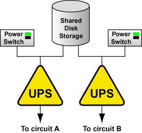
If the cluster disk storage subsystem has two power supplies with separate power cords, set up two UPS systems, and connect one power switch (or one member's power cord if not using power switches) and one of the storage subsystem's power cords to each UPS system. A redundant UPS system configuration is shown in Figure 2-3.
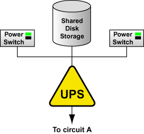
An alternative redundant power configuration is to connect the power switches (or the members' power cords) and the disk storage subsystem to the same UPS system. This is the most cost-effective configuration, and provides some protection against power failure. However, if a power outage occurs, the single UPS system becomes a possible single point of failure. In addition, one UPS system may not be able to provide enough power to all the attached devices for an adequate amount of time. A single UPS system configuration is shown in Figure 2-4.
Many vendor-supplied UPS systems include Red Hat Enterprise Linux applications that monitor the operational status of the UPS system through a serial port connection. If the battery power is low, the monitoring software initiates a clean system shutdown. As this occurs, the cluster software is properly stopped, because it is controlled by a SysV runlevel script (for example, /etc/rc.d/init.d/clumanager).
Refer to the UPS documentation supplied by the vendor for detailed installation information.
2.4.4. Configuring Shared Disk Storage
In a cluster, shared disk storage is used to hold service data and two partitions (primary and shadow) that store cluster state information. Because this storage must be available to all members, it cannot be located on disks that depend on the availability of any one member. Refer to the vendor documentation for detailed product and installation information.
There are some factors to consider when setting up shared disk storage in a cluster:
External RAID
It is strongly recommended to use use RAID 1 (mirroring) to make service data and the shared cluster partitions highly available. Optionally, parity RAID can also be employed for high-availability. Do not use RAID 0 (striping) alone for shared partitions because this reduces storage availability.
Multi-initiator SCSI configurations
Multi-initiator SCSI configurations are not supported due to the difficulty in obtaining proper bus termination.
The Red Hat Enterprise Linux device name for each shared storage device must be the same on each member. For example, a device named /dev/sdc on one member must be named /dev/sdc on the other cluster members. Using identical hardware for all members usually ensures that these devices are named the same.
A disk partition can be used by only one cluster service.
Do not include any file systems used in a cluster service in the member's local /etc/fstab files, because the cluster software must control the mounting and unmounting of service file systems.
For optimal performance of shared file systems, make sure to specify a 4 KB block size with the -b option to mke2fs. A smaller block size can cause long fsck times. Refer to Section 2.4.4.6 Creating File Systems.
The following list details parallel SCSI requirements, and must be adhered to when parallel SCSI buses are employed in a cluster environment:
SCSI buses must be terminated at each end, and must adhere to length and hot plugging restrictions.
Devices (disks, host bus adapters, and RAID controllers) on a SCSI bus must have a unique SCSI identification number.
Refer to Section D.2 SCSI Bus Configuration Requirements for more information.
It is strongly recommended to connect the storage enclosure to redundant UPS systems for a highly-available source of power. Refer to Section 2.4.3 Configuring UPS Systems for more information.
Refer to Section 2.4.4.1 Setting Up a Single-initiator SCSI Bus and Section 2.4.4.2 Setting Up a Fibre Channel Interconnect for more information about configuring shared storage.
After setting up the shared disk storage hardware, partition the disks and then either create file systems or raw devices on the partitions. Two raw devices must be created for the primary and the shadow shared cluster partitions. Refer to Section 2.4.4.3 Configuring Shared Cluster Partitions, Section 2.4.4.4 Partitioning Disks, Section 2.4.4.5 Creating Raw Devices, and Section 2.4.4.6 Creating File Systems for more information.
2.4.4.1. Setting Up a Single-initiator SCSI Bus
A single-initiator SCSI bus has only one member connected to it, and provides host isolation and better performance than a multi-initiator bus. Single-initiator buses ensure that each member is protected from disruptions due to the workload, initialization, or repair of the other members.
When using a single- or dual-controller RAID array that has multiple host ports and provides simultaneous access to all the shared logical units from the host ports on the storage enclosure, the setup of the single-initiator SCSI buses to connect each cluster member to the RAID array is possible. If a logical unit can fail over from one controller to the other, the process must be transparent to the operating system. Note that some RAID controllers restrict a set of disks to a specific controller or port. In this case, single-initiator bus setups are not possible.
A single-initiator bus must adhere to the requirements described in Section D.2 SCSI Bus Configuration Requirements.
To set up a single-initiator SCSI bus configuration, the following is required:
Enable the on-board termination for each host bus adapter.
Enable the termination for each RAID controller.
Use the appropriate SCSI cable to connect each host bus adapter to the storage enclosure.
Setting host bus adapter termination is usually done in the adapter BIOS utility during member boot. To set RAID controller termination, refer to the vendor documentation. Figure 2-5 shows a configuration that uses two single-initiator SCSI buses.
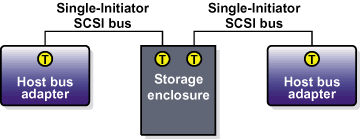
Figure 2-6 shows the termination in a single-controller RAID array connected to two single-initiator SCSI buses.
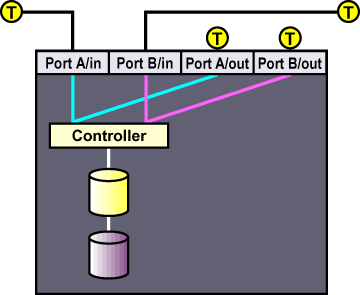
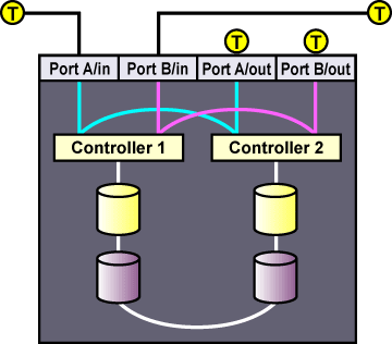
Figure 2-7 shows the termination in a dual-controller RAID array connected to two single-initiator SCSI buses.
2.4.4.2. Setting Up a Fibre Channel Interconnect
Fibre Channel can be used in either single-initiator or multi-initiator configurations.
A single-initiator Fibre Channel interconnect has only one member connected to it. This may provide better host isolation and better performance than a multi-initiator bus. Single-initiator interconnects ensure that each member is protected from disruptions due to the workload, initialization, or repair of the other member.
If employing a RAID array that has multiple host ports, and the RAID array provides simultaneous access to all the shared logical units from the host ports on the storage enclosure, set up single-initiator Fibre Channel interconnects to connect each member to the RAID array. If a logical unit can fail over from one controller to the other, the process must be transparent to the operating system.
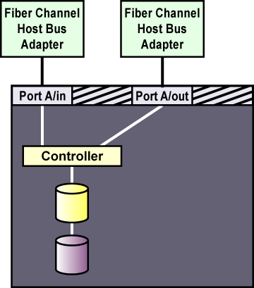
Figure 2-8 shows a single-controller RAID array with two host ports and the host bus adapters connected directly to the RAID controller, without using Fibre Channel hubs or switches. When using this type of single-initiator Fibre Channel connection, your RAID controller must have a separate host port for each cluster member.
The external RAID array must have a separate SCSI channel for each cluster member. In clusters with more than two members, connect each member to a different SCSI channel on the RAID array, using a single-initiator SCSI bus as shown in Figure 2-8.
To connect multiple cluster members to the same host port on the RAID array, use an FC hub or switch. In this case, each HBA is connected to the hub or switch, and the hub or switch is connected to a host port on the RAID controller.
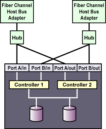
A Fibre Channel hub or switch is also required with a dual-controller RAID array with two host ports on each controller. This configuration is shown in Figure 2-9. Additional cluster members may be connected to either Fibre Channel hub or switch shown in the diagram. Some RAID arrays include a built-in hub so that each host port is already connected to each of the internal RAID controllers. In this case, an additional external hub or switch may not be needed.
2.4.4.3. Configuring Shared Cluster Partitions
Two raw devices on shared disk storage must be created for the primary shared partition and the shadow shared partition. Each shared partition must have a minimum size of 10 MB. The amount of data in a shared partition is constant; it does not increase or decrease over time.
The shared partitions are used to hold cluster state information, including the following:
Cluster lock states
Service states
Configuration information
Periodically, each member writes the state of its services to shared storage. In addition, the shared partitions contain a version of the cluster configuration file. This ensures that each member has a common view of the cluster configuration.
If the primary shared partition is corrupted, the cluster members read the information from the shadow (or backup) shared partition and simultaneously repair the primary partition. Data consistency is maintained through checksums, and any inconsistencies between the partitions are automatically corrected.
If a member is unable to write to both shared partitions at startup time, it is not allowed to join the cluster. In addition, if an active member can no longer write to both shared partitions, the member removes itself from the cluster by rebooting (and may be remotely power cycled by a healthy member).
The following are shared partition requirements:
Both partitions must have a minimum size of 10 MB.
Shared partitions must be raw devices. They cannot contain file systems.
Shared partitions can be used only for cluster state and configuration information.
The following are recommended guidelines for configuring the shared partitions:
It is strongly recommended to set up a RAID subsystem for shared storage, and use RAID 1 (mirroring) to make the logical unit that contains the shared partitions highly available. Optionally, parity RAID can be used for high availability. Do not use RAID 0 (striping) alone for shared partitions.
Place both shared partitions on the same RAID set, or on the same disk if RAID is not employed, because both shared partitions must be available for the cluster to run.
Do not put the shared partitions on a disk that contains heavily-accessed service data. If possible, locate the shared partitions on disks that contain service data that is rarely accessed.
Refer to Section 2.4.4.4 Partitioning Disks and Section 2.4.4.5 Creating Raw Devices for more information about setting up the shared partitions.
Refer to Section 3.5 Editing the rawdevices File for information about editing the rawdevices file to bind the raw character devices to the block devices each time the members boot.
2.4.4.4. Partitioning Disks
After shared disk storage hardware has been set up, partition the disks so they can be used in the cluster. Then, create file systems or raw devices on the partitions. For example, two raw devices must be created for the shared partitions using the guidelines described in Section 2.4.4.3 Configuring Shared Cluster Partitions.
Use parted to modify a disk partition table and divide the disk into partitions. While in parted, use the p to display the partition table and the mkpart command to create new partitions. The following example shows how to use parted to create a partition on disk:
Invoke parted from the shell using the command parted and specifying an available shared disk device. At the (parted) prompt, use the p to display the current partition table. The output should be similar to the following:
Disk geometry for /dev/sda: 0.000-4340.294 megabytes
Disk label type: msdos
Minor    Start       End     Type      Filesystem  Flags
Decide on how large of a partition is required. Create a partition of this size using the mkpart command in parted. Although the mkpart does not create a file system, it normally requires a file system type at partition creation time. parted uses a range on the disk to determine partition size; the size is the space between the end and the beginning of the given range. The following example shows how to create two partitions of 20 MB each on an empty disk.
(parted) mkpart primary ext3 0 20
(parted) mkpart primary ext3 20 40
(parted) p
Disk geometry for /dev/sda: 0.000-4340.294 megabytes
Disk label type: msdos
Minor    Start       End     Type      Filesystem  Flags
1          0.030     21.342  primary
2         21.343     38.417  primary
When more than four partitions are required on a single disk, it is necessary to create an extended partition. If an extended partition is required, the mkpart also performs this task. In this case, it is not necessary to specify a file system type.
Note Only one extended partition may be created, and the extended partition must be one of the four primary partitions.
(parted) mkpart extended 40 2000
(parted) p
Disk geometry for /dev/sda: 0.000-4340.294 megabytes
Disk label type: msdos
Minor    Start       End     Type      Filesystem  Flags
1          0.030     21.342  primary
2         21.343     38.417  primary
3         38.417   2001.952  extended
An extended partition allows the creation of logical partitionsinside of it. The following example shows the division of the extended partition into two logical partitions.
(parted) mkpart logical ext3 40 1000
(parted) p
Disk geometry for /dev/sda: 0.000-4340.294 megabytes
Disk label type: msdos
Minor    Start       End     Type      Filesystem  Flags
1          0.030     21.342  primary
2         21.343     38.417  primary
3         38.417   2001.952  extended
5         38.447    998.841  logical
(parted) mkpart logical ext3 1000 2000
(parted) p
Disk geometry for /dev/sda: 0.000-4340.294 megabytes
Disk label type: msdos
Minor    Start       End     Type      Filesystem  Flags
1          0.030     21.342  primary
2         21.343     38.417  primary
3         38.417   2001.952  extended
5         38.447    998.841  logical
6        998.872   2001.952  logical
A partition may be removed using parted's rm command. For example:
(parted) rm 1
(parted) p
Disk geometry for /dev/sda: 0.000-4340.294 megabytes
Disk label type: msdos
Minor    Start       End     Type      Filesystem  Flags
2         21.343     38.417  primary
3         38.417   2001.952  extended
5         38.447    998.841  logical
6        998.872   2001.952  logical
After all required partitions have been created, exit parted using the quit command. If a partition was added, removed, or changed while both members are powered on and connected to the shared storage, reboot the other member for it to recognize the modifications. After partitioning a disk, format the partition for use in the cluster. For example, create the file systems or raw devices for shared partitions. Refer to Section 2.4.4.5 Creating Raw Devices and Section 2.4.4.6 Creating File Systems for more information.
For basic information on partitioning hard disks at installation time, refer to the Red Hat Enterprise Linux Installation Guide.
2.4.4.5. Creating Raw Devices
After partitioning the shared storage disks, create raw devices on the partitions. File systems are block devices (for example, /dev/sda1) that cache recently-used data in memory to improve performance. Raw devices do not utilize system memory for caching. Refer to Section 2.4.4.6 Creating File Systems for more information.
Red Hat Enterprise Linux supports raw character devices that are not hard-coded against specific block devices. Instead, Red Hat Enterprise Linux uses a character major number (currently 162) to implement a series of unbound raw devices in the /dev/raw/ directory. Any block device can have a character raw device front-end, even if the block device is loaded later at run time.
To create a raw device, edit the /etc/sysconfig/rawdevices file to bind a raw character device to the appropriate block device to enable the raw device to be opened, read, and written.
Shared partitions and some database applications require raw devices, because these applications perform their own buffer caching for performance purposes. Shared partitions cannot contain file systems because if state data was cached in system memory, the members would not have a consistent view of the state data.
Raw character devices must be bound to block devices each time a member boots. To ensure that this occurs, edit the /etc/sysconfig/rawdevices file and specify the shared partition bindings. If using a raw device in a cluster service, use this file to bind the devices at boot time. Refer to Section 3.5 Editing the rawdevices File for more information.
After editing /etc/sysconfig/rawdevices, the changes take effect either by rebooting or by execute the following command:
service rawdevices restart |
Query all the raw devices by using the command raw -aq. The output should be similar to the following:
/dev/raw/raw1 bound to major 8, minor 17 /dev/raw/raw2 bound to major 8, minor 18 |
Note that, for raw devices, no cache coherency exists between the raw device and the block device. In addition, requests must be 512-byte aligned both in memory and on disk. For example, the standard dd command cannot be used with raw devices because the memory buffer that the command passes to the write system call is not aligned on a 512-byte boundary.
For more information on using the raw command, refer to the raw(8) man page.
| Note |
|---|---|
The same raw device names (for example, /dev/raw/raw1 and /dev/raw/raw2) must be used on all cluster members. |